Contents
- Index
Phase Response and Compensation
The choice of window edges around the impulse response does not generally affect the phase response that shows in the resulting frequency response graph, provided that the impulse response does fall within the window and that interference from reflections included don't corrupt the overall response. How far to the right of 0 seconds the actual acoustic impulse response begins represents delay which DOES strongly affect phase.
This is important to keep in mind particularly when using Photosync with the Photolink device and OmniMic40k to include true distanc travel in the measurement. In that case, the impulse response will be shown at some distance to the right, depending on the "time of flight" or how long it took the sound to get from the loudspeaker to the Omnimic due to the finite speed of sound travel. The frequency response magnitude will not be affected, but its phase response will be strongly effected because time delay increases downward phase shift proportional to the frequency of each data point. That will usually make the phase graph too busy, with phase repeatedly crossing the +/-180 degree wrap-around limits*. So to make it more comprehensible you can compensate the phase response with a negative delay value in the control at the bottom right of the frequency response graph below the "show phase" checkbox. 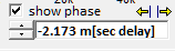
When you enable Photosync, a control box will appear labeled "Driver measurement: Time and Level Control". On it, there is a section "Auto Adjust Phase Delay To:" that you can use to configure how you want the delay control to get its value.
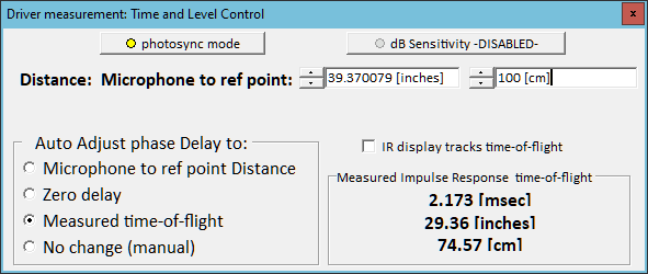 Microphone to reference point distance: compensates for the delay caused by time sound takes to travel the distance manually entered at the top. Use an accurate measure of the distance. This is the method to use when generating data files of drivers for crossover network design.
Zero delay.... just the number 0 seconds.
Measured time-of-flight: how much time passed between when the signal appeared at the speaker terminals as sensed by PhotoLink, and when the largest peak of its impulse response arrived at the OmniMic40k. This will automatically track if you change the microphone position.
No change (manual). Use the delay control at bottom right of the frequency response graph to set the value manually (for a known delay or per the desired appearance of the phase curve).
Microphone to reference point distance: compensates for the delay caused by time sound takes to travel the distance manually entered at the top. Use an accurate measure of the distance. This is the method to use when generating data files of drivers for crossover network design.
Zero delay.... just the number 0 seconds.
Measured time-of-flight: how much time passed between when the signal appeared at the speaker terminals as sensed by PhotoLink, and when the largest peak of its impulse response arrived at the OmniMic40k. This will automatically track if you change the microphone position.
No change (manual). Use the delay control at bottom right of the frequency response graph to set the value manually (for a known delay or per the desired appearance of the phase curve).
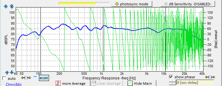
Delay uncompensated:
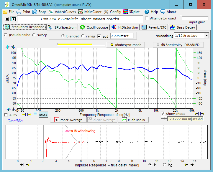
Delay Compensated for Measured Time-of-Flight:
*Phase is periodic. For instance at any one point, +180 degrees = -180 degrees = *540 degrees = -540 degrees, etc. Mathematically, any phase number plus or minus 360 degrees is exactly the same. The graph will wrap around the phase curve within -180 to +180 degrees as that is all that can be determined at any one frequency. Expressing as an unwrapped phase curve is possible, but necessarily assumptions must be made about how the result was reached from one frequency to the next --- did the true curve wrap around the +/-180 border to get there, or was it direct?