Contents
- Index
Using the OmniMic PhotoLink device
The PhotoLink has two main functions, time synchronization and setting of nominal drive levels.
The first function is to transmit a timing Optical Syncrhonization signal via modulated infrared light to an OmniMic40k microphone. Note that "Photosync" refers to the technique of syncronizing timeing via a light signal, while "PhotoLink" refers to the device that is used to accomplish this. It is primarily intended for measuring drivers for speaker design with true phase delay included and to account for time-of-flight effects of sound through the air to the microphone. In multi-way loudspeakers, the way that various drivers interract is affected by their relative distances from the listener/microphone and the "starting point" of drivers varies with their construction. When making FRD frequency response data files with optical syncronization for crossover design, the included delay should be compensated per the measured distance of the microphone tip to the mounting baffle surface the drivers are on. Also, the measurements should be made in "dB sensitivity mode" to account for driver sensitivities (see below). This will keep driver measurements compatible with others done the same way to allow you to investigate different combinations with a crossover simulator.
Optical synchronization can also be useful when measuring subwoofers should the speaker output lack sufficient higher frequency energy for OmniMic's automatic acoustic synch to align with the stimulus. In such cases, the PhotoLink device should be driven by full bandwidth signal through a separate amplifier rather than by the signal that is presented to the subwoofer terminals.
Optical syncrhonization (or "photosync`") is similar to the wired "loopback" technique used with some measurements systems, except Photosync still allows for OmniMic's wireless advantage that lets you quickly and conveniently measure without stretching cables around the room. Optical synch requires an OmniMic40k type microphone and PhotoLink device.
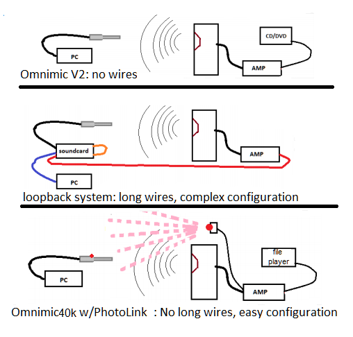
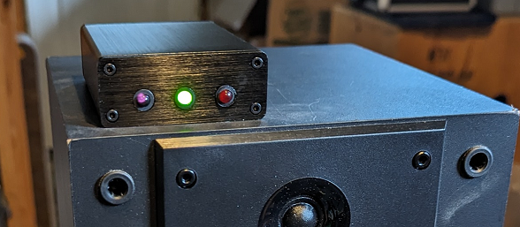
To use optical syncrhonization, the leads from the PhotoLink should be clipped to the speaker terminals or the amplifier output, with the PhotoLink placed and oriented so that its infrared LED can be "seen" by the black sensor that is on the OmniMic40k body. This can work up to about 20 feet away, and usually even just being exposed to the reflection of the infrared signal off of a nearby wall or ceiling will be enough for the OmniMic40k to syncronize with.
The OmniMic version 6 software can be used without photosync or with. Photosync is only used when in Frequency Response mode with "Sine Sweep" stimulation, and when the photosync button on the OmniMic Frequency Response screen is enabled. Photosync is not required for most measurements, but can simplify obtaining FRD files to be used for loudspeaker design and for more accurate polar data collection. Frequency response measurements (such as for room EQ or completed speaker evaluation) that don't require absolute phase delay information can and usually should be made without Photosync.
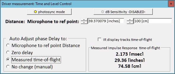
When using optical syncrhonization, you can select how this affects the applied delay to the viewed response using the Time and Level Control. For example, an impulse response that includes acoustical 'time of flight' would naturally show effects of significant delay, which could cause the displayed phase response to be difficult to interpret. Taking out delay according to the time of flight or to known distance from the speaker can be used to account for that.
The second Photolink function is to indicate to the user when the voltage level of a sweep signal applied to a speaker or driver is at the standard 2.83 Vrms for proper sensitivity measurement of a loudspeaker or for setting levels for a compression test. This second function will work with either OmniMic or OmniMic40k hardware. Remember that only sweep type signals (not noise or tones) will giver proper indication of drive level.
Sensitivity measured to a common standard (equivalent to 2.83Vrms drive with SPL measured at 1m distance) is a requirement when maintaining or sharing a library of driver curves for use with a crossover simulation program like Xsim. The scale of graphs measured this way can be displayed as "dBSPL/1m" rather than "dBSPL". OmniMic software can also account for the effects of distances other than 1m from the loudspeaker, assuming a theoretical falloff rate of 6dB per each doubling of distance.
The PhotoLink has two visible LEDs, one GREEN, one RED. The GREEN lights when there is ENOUGH signal level (for both target level and for Photosync function), the RED lights when there is TOO MUCH signal above the target SPL level (but Photosync will still work with red). When setting sweep levels for 2.83Vrms (equivalent to 1W at 8 ohms or 2W at 4 ohms), aim to adjust to where the GREEN LED blinks with each sweep but the RED does NOT. When using the computer's sound output or DAC to generate the sweep signal, you can use the "Soundcard Output Level" from the Config menu to fine adjust the level.
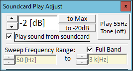
The Sweep Frequency Range should be "full band" and the signal at the loudspeaker terminals must be from a flat un-equalized setting when using the PhotoLink device for signal level setting. Equalization or bandlimiting of the sweep signal seen by the PhotoLink will result in incorrect determination of the applied signal level.
Further, only the OmniMic "short sweep" test signal (as used for frequency response measurements) should be used for setting the signal level with the PhotoLink. A continuous sine-wave or noise type signal cannot accurately be used for this. However, once levels are set using the Short Sweep signal, the same level will be correct if you change to one of the other test tabs such as Distortion, SPL, or Reverb. You can limit the Sweep Frequency Range after setting proper level with the "Soundcard Output Level" first set to "full band", and the levels over the specified range will be at the determined level.
For optical time synchronization, the PhotoLink can also be operated at levels well above where the RED LED lights, up to about 350W/8 ohms.
What if you want to set to a level other than 2.83Vrms?
If you, for example, wanted to set to a level that is 3dB higher than 2.83Vrms:
You would first set the Soundcard Output Level to a lower value (-3dB or lower).
Adjust the system (amplifier or Windows sound control level) and use the PhotoLink device so the sweep shows the green but, not the red, LEDs.
Then set the Soundcard Output Level to 3dB higher than you had it. The output voltage would then be set to 2.83Vrms+3dB, which is 4Vrms.